Gantry Automation for Industrial Manufacturing

On a gantry-loaded machining line, most of the achievable cycle time is committed at the layout stage. The number of machines one gantry serves, the position of every part buffer and the span of each beam are fixed long before anyone writes PLC code. When the controls team reaches site, those choices already exist as fabricated steel and grouted column bases. The most valuable hours of manufacturing engineering services on a gantry project are therefore the early ones, when a change still costs a drawing revision rather than a new beam.
The controls work still matters. It inherits whatever the layout allows.
Where Gantry Automation Is Decided Before the First Drawing Is Released
The first number to settle is the machine-to-gantry ratio. A single gantry serving several machines has to complete its travel, unload and reload for each of them inside the shortest machining cycle on that beam. If the loop runs longer, the spindles wait. A double gripper shortens the loop where the machine’s loading area permits it, because one visit removes the finished part and loads the raw one. Adding one more machine to the beam late in design looks like free capacity on a spreadsheet and often makes the gantry the bottleneck of the whole line.
Part buffers decide how much of that timing risk the line can absorb. A buffer station lets the gantry work ahead during short cycles and catch up during long ones. Without one, every tool change or in-process measurement stop on a single machine travels down the beam to its neighbours. Buffers also occupy floor space inside the fenced zone, so their positions belong in the first layout issue.
Beam span is a structural question with a positioning consequence. A long unsupported span deflects under the moving carriage load and vibrates after each stop. The gripper then loses positioning accuracy and waits longer to settle before a load or unload can begin. The options are a stiffer section, intermediate columns or a shorter span with a second gantry. Each one moves a problem somewhere else. Intermediate columns can block maintenance access to a machine, and a second gantry adds a transfer point between two controllers.
Carriage count follows from the ratio. Two carriages on a common beam raise throughput, but they share the same travel path. Someone has to define collision zones, interlocked handover positions and priority rules for them, and that definition starts as a layout decision before it becomes controls logic.
Safety fencing is the last decision and the easiest to underrate. The fence line follows the full travel envelope of the gantry, overtravel included, and it must leave operators access to machine doors, tool magazines and coolant units. A fence drawn after everything else is placed tends to be routed around obstacles. A fence drawn with the layout can keep access doors short and the interlock count low.
The six layout decisions below each fix a downstream constraint, and each becomes expensive once the line is installed.
| Decision fixed at layout | What it constrains later | Cost of changing it after installation |
| Machine-to-gantry ratio | Line cycle time and gantry utilisation | An additional gantry or a resequenced beam |
| Buffer station positions | Tolerance to tool changes and measurement stops | Fence relocation and lost floor space inside the cell |
| Beam span and supports | Positioning accuracy and settling time at the gripper | A re-fabricated beam or new columns and foundations |
| Carriage count per beam | Collision zones and handover logic | Rewritten transfer logic and fresh safety validation |
| Conveyor entry and exit points | Part flow to upstream and downstream processes | Conveyor rerouting and revised interfaces |
| Fence line and access doors | Maintenance access and interlock count | New panels and doors plus safety revalidation |
What a 21-Machine Crankshaft Line Asks of the Layout
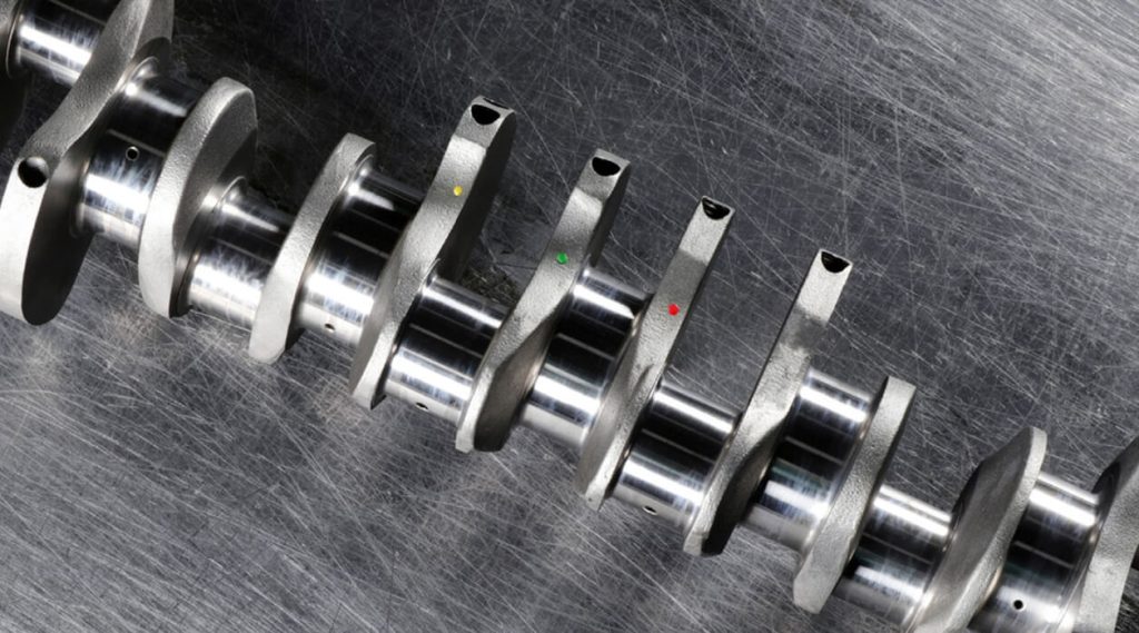
Tooltech’s work on a crankshaft machining line with 21 machines is the closest reference for these decisions. The scope covered a detailed plant and gantry layout and the design of operation stations, beams, carriages, safety fences and conveyors, with manufacturing drawings and the BOM to follow. Those elements map onto most rows of the table above, so the decisions that fix cycle time sat within one engineering scope.
The line had existing plans to align with. The team used SolidWorks, AutoCAD and Microstation V8i to bring the 2D layouts into a single 3D model that matched those plans. On a line of 21 machines that step matters. A carriage envelope passing close to overhead services or a beam height that fouls an upward-opening machine door is a vertical clash, and a plan view carries no information about either. Unmodelled, such clashes surface during installation. Execution ran over 12 months on a hybrid onsite-offshore model.
Manufacturing Engineering Services Across Layout, Controls and Handover
The crankshaft project covered layout and mechanical design. A complete gantry line also needs a control systems architecture, PLC and HMI programming, systems integration and commissioning. Tooltech’s Factory 4.0 scope lists these next to plant layout design and cycle time optimisation. Holding both halves in one scope gives traceability. Collision zones, handover positions and interlock counts defined during layout reach the controls engineers as design intent, with the reasoning attached.
A longer engagement shows the combination in practice. For a German automotive systems supplier, a fixed multidisciplinary team covering mechanical, electrical and commissioning resources has worked with the client for more than eight years through a Mix Model. Recent work focuses on the design of stations, gantry and material handling systems for the client’s EV manufacturing plants. The same engagement has placed engineers onsite at the client’s end-client plants in China and America to assist with controls and commissioning. For a plant engineering head, the relevant point is continuity. The engineers who design the stations and gantry systems sit in the same team that supports controls and commissioning.
For heavy machinery and powertrain OEMs planning a gantry-loaded line, the useful thing to establish early is how many layout decisions the engineering partner will own. A partner given only the controls scope will program around whatever the layout fixed. A partner involved from the first layout issue can still move a buffer, shorten a span or redraw a fence line while each change costs a revision.
Frequently Asked Questions
When does gantry loading suit a machining line better than a robot cell?
Gantry loading suits lines where several machines stand in a row and parts move along one main axis. The overhead structure keeps the floor in front of the machines clear for operators and maintenance crews. A robot cell suits compact groups of two or three machines, or parts that need complex reorientation between operations, where the robot’s reach covers the cell without a long travel axis.
Can an existing manually loaded line be converted to gantry automation?
In many cases it can, although the building and the machines both need checking first. Column positions need adequate foundations or floor capacity, and the full travel path has to be clear of cranes, ducting and cable trays overhead. Each machine also needs a loading door that opens to the top and a control interface able to exchange door, clamping and cycle signals with the gantry controller.
What information should a manufacturer share at the start of a gantry layout study?
The useful starting set is existing plant layouts in AutoCAD or PDF form, machine footprints with loading door positions, part drawings showing weights and gripping surfaces and the target cycle time for the line. Company standards for fencing, guarding and preferred component suppliers matter too. A layout drawn to the wrong standard will be redrawn at the first client review.
Related Insights

Engineering Document Traceability in Regulated Man...
Know More
Engineering Change Management in Complex Product D...
Know More