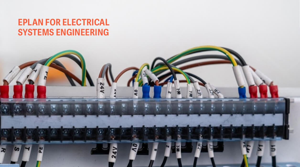
EPLAN for Electrical Systems Engineering
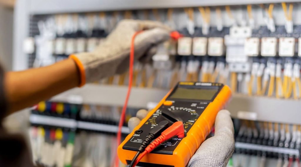
A commissioning engineer at an open control panel works from one reference: the drawing set. Terminal numbers, device tags, cable cores and PLC addresses on those pages are what every point-to-point check, loop test and I/O verification is measured against. During control system commissioning, a mismatch between the drawings and the wiring creates two jobs: tracing the fault, then deciding whether the panel or the page is wrong.
On many automated lines, that drawing set comes out of EPLAN. The condition of the EPLAN project therefore decides how much of the site programme goes on proving control logic and how much goes on reconciling documents.
FAT, I/O simulation and loop checks catch many errors before a panel ships. Each of them compares the panel against its drawings. Where the drawings carry an error and the panel builder has wired it faithfully, the check passes, and the error surfaces during commissioning.
What Control System Commissioning Inherits from the EPLAN Project
Every EPLAN report draws on one device database, so an error entered once reaches the terminal diagrams, cable lists, PLC assignment overview and bill of materials in identical form. A PLC card placed in the wrong rack slot appears identically on every page that references it, and the project raises no warning.
The second weakness sits outside the software. Between design release and site, three parties can change the electrical definition of a machine. The panel builder marks up a moved terminal by hand. The controls engineer reassigns an input because a card ran out of spare channels. The designer revises the schematic for a late customer request. EPLAN can exchange PLC hardware configuration with environments such as Siemens TIA Portal, but only when someone runs the exchange after each change. When nobody does, the schematic, the PLC configuration and the built panel reach site in three different states.
Five Data Sets the Site Team Works From
| EPLAN data set | Site check that depends on it | Symptom on site when it is wrong |
| Device tags and IEC 81346 structure identifiers | Locating field devices in the cabinet | Labels on site cannot be traced to a schematic page |
| Terminal diagrams | Point-to-point and continuity checks | Correct wiring flagged as faulty, or a crossed core passed |
| Cable lists and core assignments | Pulling and terminating field cables | Spare cores found live, schedules that do not match the glands |
| PLC I/O assignment | Loop checks and forcing of outputs | A forced output drives the wrong actuator |
| Safety circuit pages | Validation of interlocks and emergency stops | Interlock tests pass on the drawn path while the built circuit differs |
The PLC assignment row is the hardest to keep correct because it sits between two disciplines. The electrical designer owns the schematic. The controls engineer owns the program. After a late I/O change, whoever edited last decides which document is correct. For a plant evaluating an electrical testing and commissioning company, a useful bid-stage question is who will hold that reconciliation during start-up, and in which tool.
What an Electrical Testing and Commissioning Company Should Hand Back in EPLAN
Every commissioning phase produces redlines. Terminals move, spare cores go into service, interposing relays are added and inputs are readdressed. If those changes stay on marked-up prints in the site office, the as-built package describes the machine as designed rather than as running. The maintenance team inherits that gap at its first fault after handover.
Keeping the project current is mainly a scheduling decision. Redlines entered into EPLAN at the close of each commissioning phase, with revision marking switched on, record what changed and why. Re-running the PLC hardware exchange after each I/O change keeps program and schematic on the same addresses. The as-built release then becomes a check instead of a reconstruction exercise weeks after the team has left site. Any commissioning contract should give this design-data update its own line item. Without one, it depends on whoever has hours left at the end of the programme.
Where Tooltech’s Electrical Work Sits in This Chain
The Electrical, Controls & Commissioning service at Tooltech runs from schematic drawings, panel layout, wire harness design and machine safety through TIA Portal work to commissioning the plant up to start of production. At plant scale, Manufacturing Engineering carries PLC and HMI programming and commissioning within the same scope as plant layout. In Tooltech’s industrial equipment lifecycle, as-built electrical and mechanical drawing packages with BOM and labels sit in the same stage as PLC programming and commissioning, which is where the redline loop runs.
The case record names EPLAN directly twice. For a German manufacturer of hydrogen filling stations, the scope included electrical circuit and layout design, SIL evaluations and ex-zone documentation, with Eplan Suite among the tools and PED, ATEX and CE compliance as requirements (Hydrogen Refuelling Station Design). For a CNC manufacturer, Tooltech engineers selected and customised variants of a universal machine using CimBase and EPLAN (Universal CNC Machine Customisation).
On the commissioning side, the nearest comparison comes from a different engagement: an offshore development centre for a German automotive systems supplier, running for more than eight years with a fixed multidisciplinary team of mechanical, electrical and commissioning resources. That team works onsite at end-client plants in China and America on controls and commissioning, and offshore on mechanical and electrical assignments including library creation. What carries across is the arrangement: design and commissioning resources held within one continuing team, which the redline loop depends on.
For a plant owner, the working test of any electrical design supplier is the state of the EPLAN project on the day the line reaches the start of production. If it matches the panels and the PLC hardware configuration, the maintenance team can work from it for the life of the line. If it lags behind them, every later modification begins with a site survey.
FAQs
When does EPLAN Pro Panel pay back on a controls project?
It pays back where panels repeat or wire counts are high, because routes and lengths from the 3D layout can feed wire preparation directly. For one-off panels with modest wiring, a 2D layout from Electric P8 is usually enough.
Can legacy AutoCAD electrical drawings be brought into EPLAN?
A plain DWG import brings in lines and text without device, connection or cross-reference data, so the imported pages cannot generate terminal diagrams or cable lists. For a machine that will be modified again, rebuilding the pages with EPLAN devices and macros is usually worth the effort. For a stable line, a PDF archive may be sufficient.
Who should own the EPLAN project after plant handover?
The plant should receive the native project in addition to PDF exports, along with the parts master data and macros the project references. Agree the EPLAN version in the contract as well, since a project saved in a newer version cannot be opened in an older one.
Related Insights

Engineering Document Traceability in Regulated Man...
Know More
Designing Infrastructure Assets for Long-Term Main...
Know More