Electronic Systems Design with Zuken
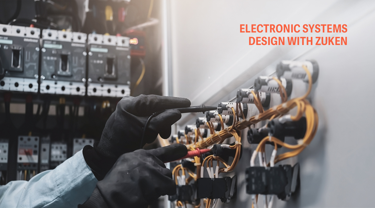
A wire list, a terminal plan and a cable schedule describe the same control panel three times. In a drawing-based workflow each one is edited as a separate document, and every late revision gives one of them a chance to fall behind the other two. The mismatch can stay hidden through the workshop stages and appear during control system commissioning, when a circuit is energised against a drawing that no longer matches the hardware.
Electrical design software decides how often that happens. Zuken, the Yokohama-based design software vendor, organises its electrical and electronic tools into two main product families. CR-8000 covers PCB and electronic system-level design. E3.series covers the electrical side of a machine or plant: schematics, cabinet layout, cables and wire harnesses. For site work, E3.series is the relevant one. Its output is what the panel builder wires against and what the site team tests against.
Where Control System Commissioning Inherits Its Faults
Factory Acceptance Testing, I/O simulation, loop checks and point-to-point checks catch a great deal before a machine is installed, and each of them verifies the build against documentation. If the documentation disagrees with itself, those checks will pass wiring that matches one drawing and contradicts another.
A device substitution or a late I/O reallocation has to be carried by hand into every document that references it. The PLC programmer works from the I/O list. The panel builder works from the layout and wire list. The field electrician works from the cable schedule. Each person is correct against their own document, and the disagreement between documents stays invisible until the machine runs.
What a Single Electrical Database Changes
E3.series is object-oriented. A device placed in the schematic is the same object in the cabinet layout and in the connection data. Change a terminal in one view and it changes in every view. Wire lists, terminal plans, cable lists and bills of material are generated from the model instead of being typed separately. Built-in design rule checks run against the same data before the design is released.
The harness side follows the same logic. Formboard drawings, connector pinouts and branch lengths come from the same connection data as the schematic, so the harness supplier and the panel builder work from identical information.
There is a limit. The model is only as reliable as its parts library. A connector modelled with the wrong pin assignment will appear wrong in every report, with complete consistency, and every downstream check will agree with it. The library needs a named owner and a release process of its own.
| Design artefact | What it can settle before site | What still waits for site commissioning |
| Schematic and device list | Circuit logic, interlock wiring, device ratings against design loads | Interlock behaviour with real field devices and real response times |
| Terminal plan and connection list | Terminal allocation, point-to-point continuity inside the panel | Terminations disturbed in transport, field wiring done by other contractors |
| Cable list with routed lengths | Cable type, core count, length from the modelled route | Tray routes where site conditions differ from the layout |
| I/O list linked to the PLC tag database | Address mapping and signal types for simulation | Sensor alignment, encoder direction, analogue scaling against real process values |
| Harness formboard drawing | Lengths, branch points, connector pinouts | Fit, bend radius and strain relief on the installed machine |
Every entry in the right-hand column depends on hardware, installation or the process itself, and none of it can be checked from a drawing. Commissioning time should be planned around that column.
What an Electrical Testing and Commissioning Company Needs from the Design Team
Site engineers work from issued data. Any electrical design, control and commissioning company inherits whatever revision discipline the design side kept, good or bad. When the schematic, terminal plan and cable list come from different releases, the first days on site go into reconciling paper instead of testing equipment.
A useful handover package has four properties. Every document comes from the same release of the model. The I/O list matches the tag database loaded into the PLC. Device designations on the drawings match the labels on the hardware. A defined route exists for site redlines to go back into the model.
That last point decides whether the connected database keeps its value after handover. Commissioning changes wiring. A sensor moves to a spare input, a relay is swapped for a different coil voltage, a cable is rerouted around an obstruction. If those changes live only as pen marks on a site drawing set, the model no longer describes the machine at handover. The as-built set should be regenerated from the corrected model, so the documentation the maintenance team receives reflects the machine they will maintain.
Design and Site Under One Scope
The Electrical, Controls & Commissioning practice at Tooltech covers both ends of this chain. On the design side, that includes electrical schematic drawings, control panel layout, wire harness design, machine safety and cable and cable tray routing. On the plant side, the Manufacturing Engineering (Factory 4.0) service carries PLC and HMI programming, systems integration and onsite commissioning through to start of production. As-built electrical and mechanical drawing packages with BOM and labels form part of the same lifecycle.
For a team reviewing its own ECAD setup, two questions give a faster read than any feature comparison: who maintains the parts library, and how site redlines return to the model. Both can be answered before the next project reaches the site.
Frequently Asked Questions
Can legacy drawings from a conventional CAD tool be moved into E3.series?
They can be brought in, but drawings from a non-intelligent CAD tool carry no device or connection data. Conversion means rebuilding that data. The parts library should be built and checked before active product lines are migrated, since every converted drawing depends on it.
When should commissioning engineers review the electrical design?
Before release to panel build. At that stage they can check I/O allocation, terminal grouping and device naming against the sequence in which the machine will be tested. A change at that stage costs a drawing revision. The same change after panel build means rewiring.
Which standards should electrical design documentation follow?
The software does not choose the standard. IReference designations commonly follow IEC 81346, documentation follows IEC 61082 and the electrical equipment of machines falls under IEC 60204-1, adopted in Europe as EN 60204-1. The project template and parts library should encode the chosen convention before the first schematic is drawn.
Related Insights

Engineering Challenges in Modernizing Legacy Indus...
Know More
Product Engineering Design: Why the Sequence Matte...
Know More