Engineering Challenges in High-Power EV Charging Station Design
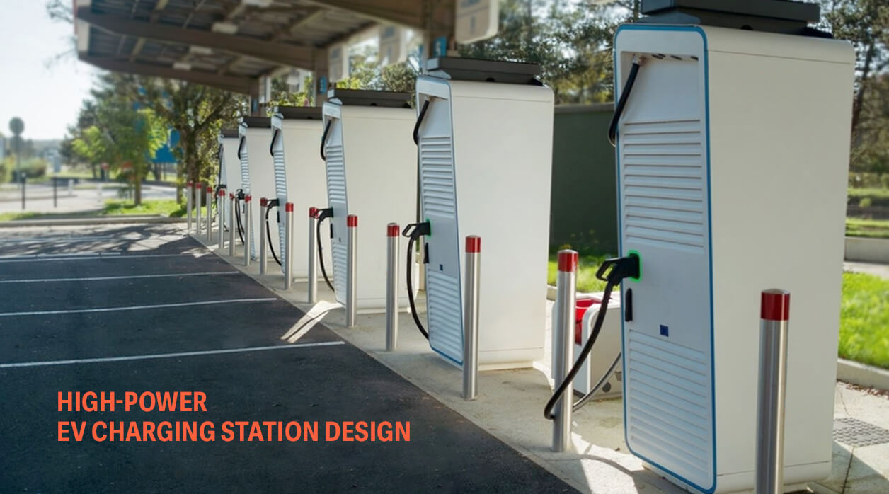
Most of the power a DC charger fails to deliver to the vehicle becomes heat inside its own cabinet. At high power, even a good efficiency figure leaves kilowatts of loss, dissipated a short distance from the control electronics, the insulation monitoring circuit and the hardware that negotiates the session with the car. That condition places the hard problems of any high-power charger programme where disciplines meet. For an engineering services company working on charging hardware, the first task is to identify which of those meeting points will decide the design.

Conversion Losses Set the Thermal Budget Before the Enclosure Exists
A typical high-power module runs a power factor correction stage followed by an isolated DC-DC stage, and both lose energy through switching and conduction. Heat concentrates in the semiconductors and magnetics, while the control board, contactors and busbars each run against temperature limits of their own.
The cooling method then constrains everything around it. Forced air needs an intake, and an intake admits the dust and moisture that the ingress protection rating has to account for. A sealed cabinet with a liquid loop keeps contamination out but adds a pump, a heat exchanger and a potential leak path near high-voltage parts. Each option moves cost and risk to a different discipline.
The thermal budget fixes heatsink size, fan or pump capacity and module spacing. When the enclosure is drawn first and the cooling fitted afterwards, the cabinet volume becomes the thermal limit and the continuous rating follows it.
Creepage, Clearance and EMC Compete for the Same Board Area
IEC 60664-1 sets creepage distances by working voltage, pollution degree and material group, and clearances by impulse withstand voltage, pollution degree and altitude. Higher output voltages raise the required spacing on boards and busbars.
Pollution degree is where the mechanical and electrical designs meet directly. The value a PCB designer assumes depends on how well the cabinet keeps out dust and condensation. A late change to the airflow path can invalidate that assumption. Creepage distances across the power boards may then need to grow, which on a dense board can mean routed slots or a new layout.
Switching noise occupies the same boards. Fast power semiconductors produce steep voltage edges, and that energy couples onto signal lines unless layout, filtering and grounding are planned together. On CCS chargers the control pilot line carries power line communication with the vehicle under ISO 15118. IEC 61851-23 also requires insulation monitoring on DC charging stations. Noise that corrupts either circuit ends the session with a communication or insulation fault, which tends to send the investigation into firmware before anyone reviews the layout.
Derating Is a Software Decision With Hardware Consequences
When temperatures climb, the control software reduces output current and communicates the lower limit to the vehicle, which adjusts its request. Derating accuracy depends on where the temperature sensors sit and how quickly they respond.
A sensor on the heatsink base reads a delayed average of what the semiconductor junction experiences. Thresholds set too tight cut current in sessions the hardware could have carried at full output. Too loose, and the protection trips the session outright.
The software team inherits these sensor and layout decisions, often without the reasoning behind them. Derating curves, sensor placement and thermal models need validation against the same test data before the curves go into firmware, because the coupled behaviour shows up only when all three run together.
The matrix maps each challenge to the three disciplines.
| Challenge | Mechanical | Hardware and PCB | Software |
| Heat path | Heatsink, airflow or liquid loop, module spacing | Component placement, sensor location | Derating thresholds and response time |
| Insulation coordination | Ingress protection that holds the assumed pollution degree | Creepage and clearance on boards and busbars | Insulation fault handling and safe shutdown |
| Switching noise | Grounding points, shielding, cable routing | Filtering, stack-up, return paths | Communication error handling |
| Vehicle communication | Connector and cable routing | Control pilot and PLC hardware | ISO 15118 session logic |
What an Engineering Services Company Has to Own Across the Cabinet
Every row in that matrix lands in all three columns. A design partner that holds only one column hands the other two a set of constraints without the reasons behind them.
Tooltech’s Energy Transformation scope for charging stations covers enclosure and cabinet design, schematic and PCB layout, thermal and electrical layout and software validation, with compliance to IEC, UL and Bharat EV specifications.
A blue-sky charger inherits no thermal budget, insulation assumption or derating policy. The design team has to set each one and hold it consistent across disciplines. The EV charging station programme for a Scandinavian EV solutions provider began on that footing, with no existing technical specifications. A multidisciplinary R&D team covered mechanical design optimised for mass production, embedded hardware design for the schematic and PCB layout and software modules with validation for charging functionality.
A welding equipment project for a Scandinavian welding solutions manufacturer serves here as an analogy, since an automated welding machine also houses high-current switching and control electronics in one enclosure. The work integrated the main circuit and EMC filter with design changes, relocated the components of the secondary diode PCB to the heatsink and rearranged the assembly so the heatsink could be commonised. The mechanical assembly was redesigned to match. A high-power charger demands the same joint handling of board and heatsink at a larger scale. The PCB side of such work sits under Electronics Engineering and Embedded Systems.
Ask a prospective design partner who sets the derating thresholds and whether that engineer has seen both the thermal model and the board layout. If the answer involves three teams and a handover document, the coupling described above tends to surface late, in type testing or in the field.
Frequently Asked Questions
Can a lower-power charger platform be scaled up to high power?
Adding power modules raises output, but busbars, contactors, fuses, the output cable and the DC connector all carry the higher current. At the top of the range the cable often needs liquid cooling to stay within connector temperature limits. Certification bodies will normally expect testing at the new rating, so plan a scaled platform as a new variant with its own verification.
When should site layout and installation planning enter the programme?
Before the cabinet layout freezes. Cable entry direction, anchoring points, service access clearances and the orientation of the cooling intake all depend on how the unit sits on site. CAD support for site layout and installation planning is part of Tooltech’s listed charging infrastructure scope.
Does a split architecture with a separate power cabinet ease these problems?
Partly. Moving conversion into a remote cabinet takes the main heat source away from the dispenser the driver uses. The dispenser still holds the cable, the control pilot hardware and often the cable cooling. The link between the two units adds a communication path and cable sizing of its own.
Related Insights
FEA-Driven Design Validation for Complex Engineeri...
Know More